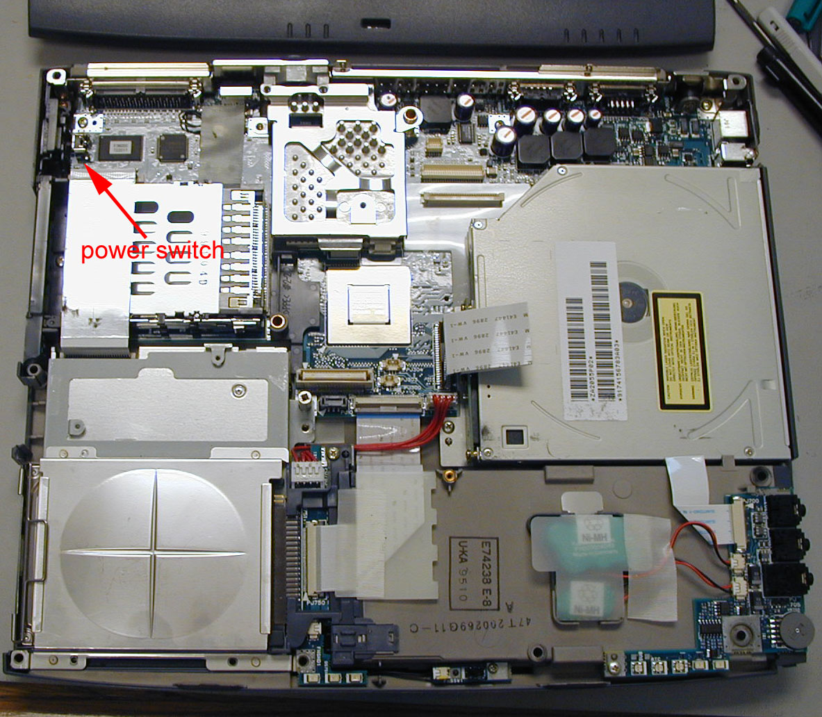
Yesterday my trusty Toshiba 2545XCDT laptop wouldn't turn on. The
power switch button didn't feel right either. There was obviously
nothing to do but open it up and see what had broken (warranty was
expired, and I couldn't spare it long enough for a depot repair
anyway). I had previously made a short-lived attempt to open the
case on the notebook to install a new hard disk drive. Before I
had proceeded too far I discovered that the hard drive could be
removed without taking apart the case (just remove the
small cover
on the left side near the front - one screw underneath). This time
it was obvious that the case would have to be disassembled.
I spent quite a bit of time searching the web for information on
taking apart Toshiba satellite notebooks, without much success. So
when I finally succeeded (with a bit of help from friends), I thought
others might benefit. I don't know how many other models these
instructions will apply to, but I would guess that any 2540, 2545, 2535, or
2595 model will come apart essentially the same way (such as 2545CDS,
2545XCDT, or 2540CDS). The switch turned out to be
quite simple to fix, requiring nothing more than a piece of paper clip.
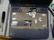
| Step 1 - Getting started
Start by turning over your laptop and taking out the battery. Take out
all the 20mm screws (which have the number 20 molded into the case
next to them) and the three shorter screws circled in the photo.
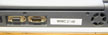
Turn it upright again and take out the two screws on
the rear side of the case.
|
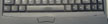
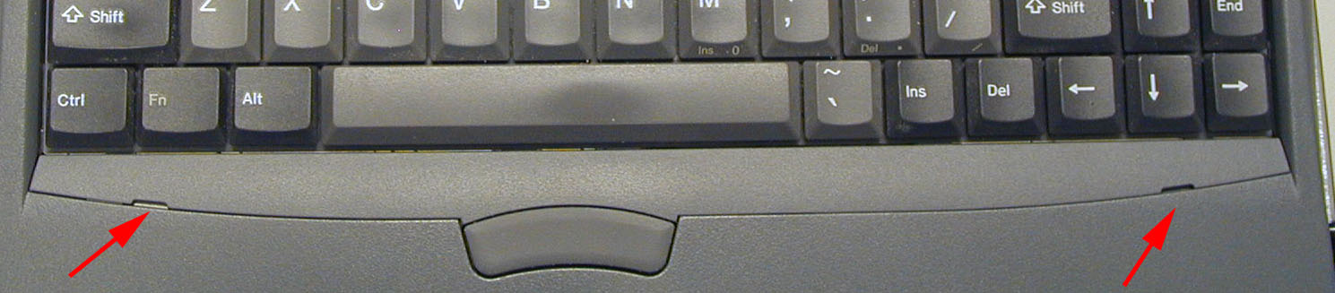
| Step 2 - Getting under the keyboard
Pop off the narrow bezel strip between the keyboard and the mouse
buttons. Use the jeweler's flat screwdriver to gently
pop the plastic latches along the front edge (start with the two visible
notches). Slide your screwdriver along the groove from each of the
notches towards the center, popping each of the other three tabs as
you go. With the front edge released, you should be able to pop up
the back edge without difficulty. Remove the very small screw holding
the metal keyboard clip in place. The keyboard will now lift out.
|
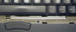
| Step 3 - Back bezel
You need to remove the odd-shaped plastic plate between the keyboard and
the display with "Toshiba" embossed on it. First remove the screw at
the left front of the bezel. Next pry gently at the right hand edge.
|
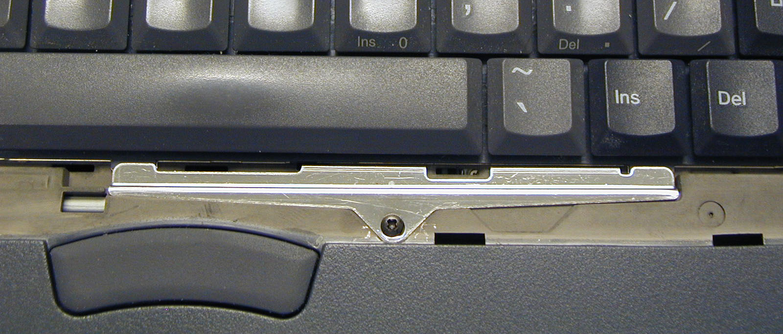
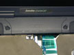
| Step 4 - Keyboard removal
After the nameplate bezel has been removed, you can remove the keyboard
by very carefully lifting each end of the flat cable connector using the
right-angle scribe or similar instrument (dental pick would do fine too).
The same tool can be used to gently pull the two cable connectors out of
their sockets as shown. You might take advantage of having the keyboard
out to blow out all the accumulated dust and hair.
|
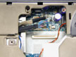
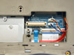
| Step 5 - Remove modem (if present)
Removing the modem provides access to another cable that must be released.
Two screws hold the modem in place, and another three screws must be
removed to free the case top half. Be careful that the weight of the
screen doesn't suddenly flip the case top backwards.
|
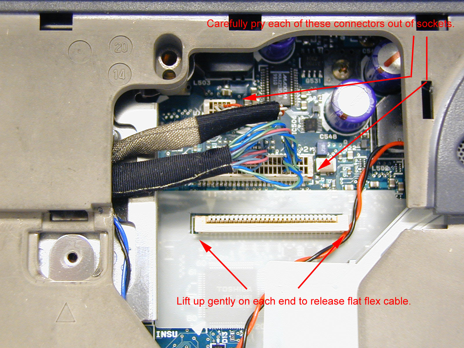
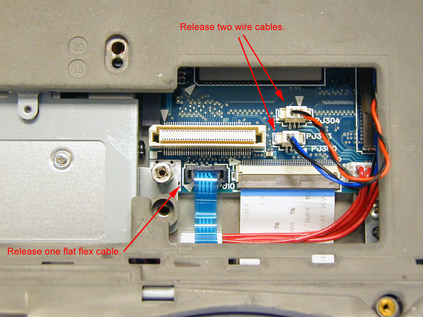
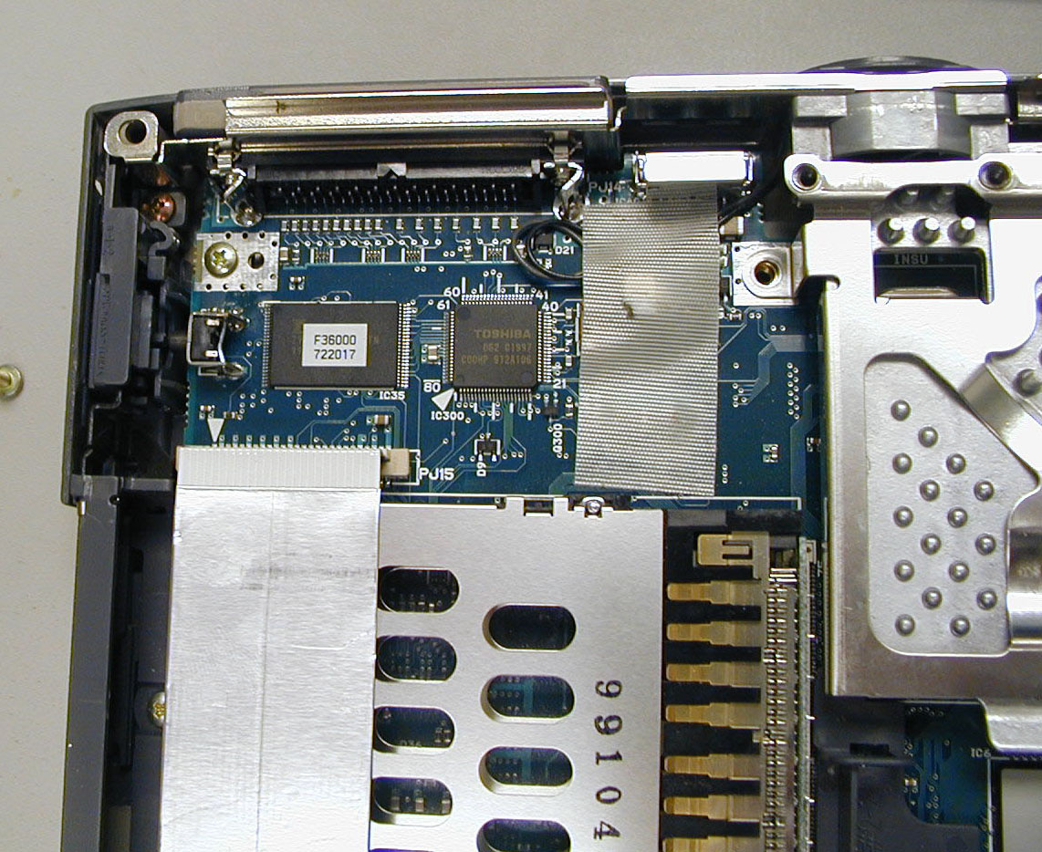
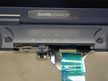
| Step 6 - Remove last cables
One more flat flex cable and two discrete wire cables under the modem must
be released. Gentle prying on each end with the right angle pick is again
called for.
|
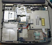
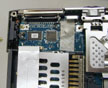

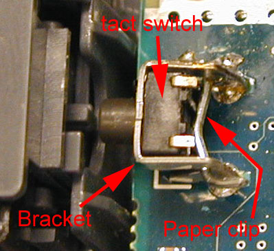
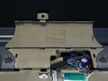
| Step 7 - Switch repair
Now that the top is finally off, the power switch repair can proceed. The
problem I discovered with the power switch was that the little "tact" switch
had been pushed out of the metal bracket by repeated presses of the plastic
button on the case. The switch had no support from the back side. My fix
was to insert a paper clip through the gap in the switch support bracket
to provide a rear brace. I bent the clip over on one side with needle
nose pliers and soldered the clip to the bracket on the other side. Other
solutions that strengthen the switch would likely work also.
|
| Step 8 - Reassembly
Reassembly is just the reverse process. Assuming you kept good track
of where each screw came from, you shouldn't have any left over (as I
did :-). Now my power switch is better than new!
|